
This project is a 5-octave MIDI controller designed to mimic instruments like a marimba, vibraphone, xylophone, etc. My main driving force behind this project was that, as percussionists know, 5-octave, 61-key mallet instruments are incredibly expensive and take up a ton of space. Add in the fact that you may want a marimba, xylophone, glockenspiel, vibraphone, etc…you’ve now invested tens of thousands of dollars and need a whole area of your house just for the mallet instruments. So I wanted to make a “simple” MIDI controller that was designed to not only be used with mallets, but provide ample space on each bar so that 4-mallet players would not struggle with accuracy. Simply plug the Teensy into your computer and use it with your preferred MIDI software. The resulting device works well with mallets and can even detect dynamics! After I finished the project in 2025, I had only invested around $300.
To see it in action, check out the video!
https://vimeo.com/1115222146?fl=pl&fe=sh
61-Key Mallet-Driven Midi Controller © 2025 by Chris Creech is licensed under Creative Commons Attribution-NonCommercial-ShareAlike 4.0 International. To view a copy of this license, visit https://creativecommons.org/licenses/by-nc-sa/4.0/
Supplies

Soldering iron
Drill
Saw
Small gauge stranded wire (22-24 gauge, approximately 330’)
122 machine screws, I used 10-24 x 1 3/4”
Longer machine screws for bars that are over supports in the middle
122 nuts to match machine screws
1/2” neoprene, approximately 2 square feet.
1/16” self-adhesive neoprene, approximately 4 square feet.
1/4” plywood or similar material, approximately 8.1 square feet. I used pegboard since I had scrap lying around.
1×4 lumber, approximately 48’ total.
Hinges, I used 3” strap hinges. These are optional, only if you want to be able to fold the instrument in half.
1 Teensy 4.1
4 CD74HC4067DB Multiplexers
Solder (I used 60/40 rosin-core)
61 20mm Piezo disc triggers
RTV sealant
61 1megohm resistors
61 3.3v Zener diodes
Wood screws (1”)
Step 1: Cut and Assemble Frame and Cut Bars
First, we’ll assemble the frame.
1.) Cut four 1x4s to 100″ each. This will allow space for all the bars plus room for the Teensy and a computer to sit on the end.
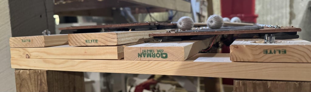
2.) For the supports, we need two 19″ 1x4s and two 9.75″ 1x4s. This will make a support for each end. Stack a 9.75″ 1×4 on a 19″ piece and screw together. Repeat that for the second support. You can see how these are aligned in the photos. If you choose to hinge the middle, you will need 2 more supports.
3.) Your final cuts will be the bars. We need 61 bars, and they need to measure 9.25″ by 2″ unless you want to edit the size. However, this will change the measurements on everything else.
4.) Taking care to space evenly (check spacing at both ends and in the middle), lay two of your 100″ 1x4s parallel down the long end of the support and secure with screws. Repeat for the raised portion of the support. This will mimic the mallet instruments raised sharp and flat keys.
Step 2: Attach Piezos to Bars

As shown in the photos, attach the piezos as close to the middle of the bars as you can get. I used RTV sealant. Superglue was not resistant to vibration, and epoxy resin seemed very brittle. A little RTV sealant on about 1/3 to 1/2 of the back of the piezo allowed the piezo to flex and vibrate as needed.
Step 3: Wire Multiplexers and Teensy
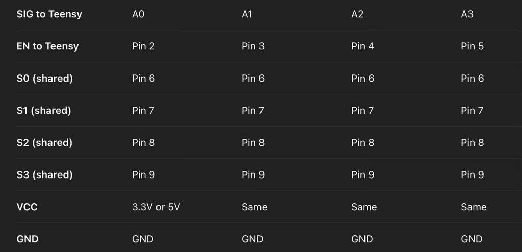
Connect the multiplexers to the Teensy as shown in the wiring table in the photos. The columns put the multiplexers in order, for example: MUX 1 SIG goes to Teensy A0, MUX1 EN goes to Teensy Pin 2, MUX 2 SIG goes to Teensy A1, etc. Any shared connections should be bundled and secured with tape, wire nuts, etc.
Step 4: Attach Bars to Frame


Each bar needs to be attached to the frame. To maintain proper spacing, I used 1/4″ spacers (you can use scrap from your 1/4″ plywood). As pictured, each bar will have 1/2″ of neoprene between the bar and the frame. I stacked two 1/4″ squares, each approximately 1.5 x 1.5 inches. Once your bar is in place, drill two holes big enough for your machine screws, one on each end of the bar. I went close to the edge of the bar so I could have more playable surface on each bar. Secure each bar with machine screws in each hole and tighten the nuts on the bottom. I also loosened each nut to have about 1/8″ space so it wasn’t tight. This allows some shock absorption and also for the keys to move slightly when played, mimicking a mallet instrument. I used superglue or Loctite to keep the nuts from vibrating loose. I then placed an adhesive-backed strip of 1/16″ neoprene on each bar.
IMPORTANT: If you choose to hinge the instrument, choose a section to place the hinges between either a B and C or an E and F. This makes sure your hinge doesn’t center on a sharp or a flat. When you know where you want it, do not add any bars after it until you cut the frame for the hinge. Add the hinge and supports, and then continue adding bars. If you don’t, your spacing will be wrong because of the blade thickness.
Step 5: Wire Piezos and Components and Wire to Multiplexers

Now wire all 61 piezos to the resistors, diodes, and multiplexers. Each resistor and diode will be wired in parallel with the piezo as pictured. The banded end of the Zener diode needs to be connected to your signal end of the piezo. You will also need to connect a signal wire to run to the multiplexers, and a ground wire will run to a common ground that will terminate with the ground wire from the Teensy. Each key is in order. For example, the first key on the board (C) will be wired to Multiplexer 1, C0. C# will be Multiplexer 1, C1. D will be Multiplexer 1, C2, etc. Once these are soldered in place, manage the cables underneath. I stapled zip ties into the frame and then used the zip ties to bundle the cables.